Linear Gradients
When CT_GradientFillProperties.lin is defined, the fill is a linear gradient fill. The linear gradient has a couple attributes: an optional 'scaled' flag that we don't have UI for (so not discussed here), and an angle, that determines the orientation of the gradient fill.
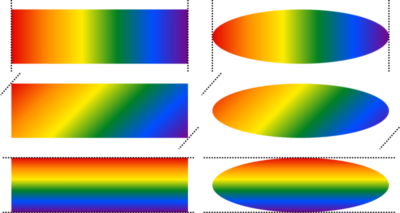
The following examples, with a Pride-month-inspired color stops, show gradients being applied at 0 degrees (top row of shapes), 45 degrees (middle), and 90 degrees (bottom). The gradient is interpolated between a range calculated from the rotation angle and the anchor rectangle bounds. Dotted lines by each example show the min/max range limits of the gradient, as it is interpolated across the shape. For a rectangular shape, where the shape path is the same as the anchor rectangle, all of the gradient colors appear in the shape (left column of diagram). When a linear gradient is applied to other shapes, the effect appears as if the shape was a stencil used to crop out the rectangular gradient.
Rectangle Gradients
The default value for CT_GradientFillProperties.path is "rect", and this type is also the easiest to explain. The gradient colors are interpolated smoothly between the focus and anchor rectangles. If the focus rect has area (i.e. it is not a point and not a line), it will be filled with the first color of the gradient.
Using the same four examples of various gradient focus rectangles, here is how gradients should be drawn with CT_PathShadeProperties.path = rect:
Path Gradients
Path Gradients with CT_GradientFillProperties.path = "shape" are similar to the "rect" case; the gradient colors are interpolated smoothly between two shapes: one sized to fit into the focus rectangle, and a second sized to fit in the anchor rectangle. If the focus rect has area (i.e. it is not a point and not a line), the shape in the focus rectangle will also be filled with the first color of the gradient.
Using the same four examples of various gradient focus rectangles, here is how gradients should be drawn with CT_PathShadeProperties.path = path:
Note that, depending on exactly how an app implements the interpolation between two shapes, there will likely be ambiguity about what color to draw for many pixels. This is especially true if the path is convex (has one or more interior angles > 180 degrees), as in this example:
There is more than one way to try and interpolate a gradient fill between two shapes, but the method Office uses in most cases is to divide the area connecting the focus and anchor shapes into quadrilaterals so that opposite edges of each quad are at the same relative position on each shape. The quads are then divided into two triangles, which are filled with a linear gradient (a simpler shape filling type that is supported by most modern graphics APIs). When this strategy is applied to convex shapes, artifacts arise when different quads overlap. The final result can be asymmetrical, and depends on the order the triangles were drawn.
Because of asymmetrical rendering artifacts like this, Office chooses to render path gradients for many preset shapes as if they were CT_GradientFillProperties.path = "circle". Office will also defer to radial gradient if the path is custom (not a preset type).
Radial Gradients
Radial path gradients are drawn when the path attribute of CT_PathShadeProperties is set to "circle". The gradient colors are interpolated smoothly between a circle that circumscribes (outer) anchor rectangle, and an ellipse. The ellipse is harder to describe; it fills the rectangle formed when the fillToRect relative rectangle is applied to the circle's bounds.
Using the same examples of gradient focus rectangles, here are the circumscribed ellipses that radial gradients will interpolate between:
In these diagrams, a circle (identical in each) circumscribes the anchor rectangle, and the bounding box of this circle is shown by a long-dashed square. In the third and fourth diagrams, dot-dash rectangles indicate the bounding box of the fillToRect rectangle, which is relative to the circle's bounding rectangle rather than the original anchor rectangle.
Note that the inner ellipse doesn't fall in exactly the same location as with the rectangular path gradient, because the inner shape is relative to the circumscribed circle.
Here are the resulting images when the gradient is interpolated between these circles/ellipses:
Radial Focus Point
2D rendering tools such as GDI+ and D2D have built-in mechanisms for drawing gradients, and they often present the concept of "focus point" - the 2D point where the gradient radiates away from. Our algorithm for calculating the radial gradient focus point is relative to the anchor rectangle and the focus rectangle.
Our PathGradientInfo takes in an anchor rectangle and a focus rectangle for determining the size and position of our inner path. On the other hand, GDI+ takes in a center point and a scaling factor pair, so that the focus path can be determined by scaling the filled path about this center point. We have to convert our rectangles into this representation, and these equations show how:
Let P be the required center point and S be the required scaling factors in two dimensions.
Let X and X' be the top-left corner of our outer and inner rectangles, respectively, and D and D' be the size of our outer and inner rectangles in two dimensions respectively.
Then we must have:
S = D' / D
( X - P ) * S + P = X'
Solving these equations for P,
P = ( X' - S * X ) / ( 1 - S )
= ( D * X' - D' * X ) / ( D - D' )
= X' + D' * ( X' - X ) / ( D - D' )
Therefore, we use this to perform our conversions:
S = D' / D
P = X' + D' * ( X' - X ) / ( D - D' )
Here is a more literal translation of our currently shipping logic, in C++-like pseudo-code. Here, "rcInner" is the focus rect, and "rcOuter" is the circumscribed rectangle around the shape bounds.
Point2D ITech::CalculateGradientOrigin(const Rect& rcInner, const Rect& rcOuter)
{
Point2D gradientOrigin = Point2D(rcInner.left, rcInner.top);
Vector2D innerRectSize = rcInner.GetSize();
Vector2D outerRectSize = rcOuter.GetSize();
if( innerRectSize.dx > 0.0 )
{
double widthDiff = outerRectSize.dx - innerRectSize.dx;
if(NotEqualToZero(widthDiff)) // This helper function performs comparison using tolerance of 2 * DBL_EPSILON
gradientOrigin.x += innerRectSize.dx * (rcInner.left - rcOuter.left) / widthDiff;
}
if( innerRectSize.dy > 0.0 )
{
double heightDiff = outerRectSize.dy - innerRectSize.dy;
if(NotEqualToZero(heightDiff))
gradientOrigin.y += innerRectSize.dy * (rcInner.top - rcOuter.top) / heightDiff;
}
return gradientOrigin;
}
' cx='32' cy='32' r='32' /%3E%3Ctext x='50%25' y='55%25' dominant-baseline='middle' text-anchor='middle' fill='%23FFF' %3ERH%3C/text%3E%3C/svg%3E)
